MM400C
LECTROSONICS, INC.
12
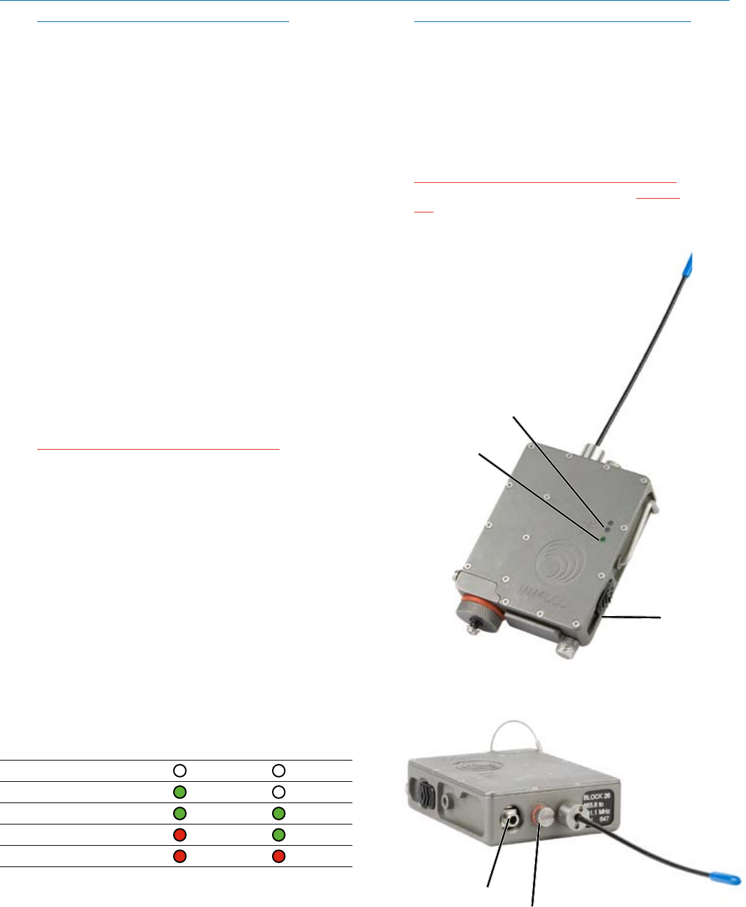
POWER
LED
Modulation
LEDs
Power On/Off
Switch
NOTE:All400Series(andanumberofearlier
receivers)offerafrontpanelLCDsthatindicatethe
correct transmitter switch settings when locating
clear channels. Use the scanning functions on
these receivers to find a clear channel, then switch
both the receiver and transmitter to the Frequency
Select Switch settings indicated in the receiver’s
display.
If you are using a 100 Series receiver, turn off the trans-
mitter and observe the RF LED on the front panel of the
UCR100 receiver. If it flickers, or glows red, then adjust
the UCR100’s Frequency Select Switches up or down in
100kHzincrementsuntiltheRFLEDextinguishes.Set
the MM400C transmitter’s Frequency Select Switches
to the same settings. Turn on the transmitter and ob-
serve that the RF LED on the receiver glows brightly.
Attaching a Microphone and
Adjusting Audio Levels
The front panel Modulation LEDs indicate limiter activity.
(Seechart.)Sincethedistortionintroducedbythelim-
iter is minimal and full modulation is assured, occasional
forays into the red by the -10 LED is acceptable.
1) Install a fresh battery.
2) Insert the watertight microphone plug into the Mic
Jack and screw it in snugly.
WARNING: Do not overtighten as this will
distort the “O-ring” and allow moisture to enter
the unit.
3) Mute the main sound system and rotate the Audio
LevelControlontheMM400Ctomaximumcounter-
clockwise(Off).
4) SetthePowerON/OFFswitchtotheONposition.
5) Position the microphone in the location where it will
be used during in actual operation.
6) ObservetheMM400CModulationLEDSwhile
speaking or singing into the microphone at
the same voice level that will be used during
the program. Gradually rotate the Audio Level
Control control clockwise until both LEDs glow
greenwiththe-20dBoccasionalblinking
red. This indicates full modulation and is the
optimum setting for the transmitter’s gain.
Signal Level -20 LED -10 LED
Lessthan-20dB Off Off
-20dBto-10dB Green Off
-10dBto+0dB
Green Green
+0dBto+10dB
Red Green
Greaterthan+10db
Red Red
NOTE:Differentvoiceswillusuallyrequiredifferent
settings of the Audio Level Control, so check
this adjustment as each new person uses the
system. If several different people will be using
the transmitter and there is not time to make the
adjustment for each individual, adjust it for the
loudest voice.
7) OncetheMM400C’saudiogainhasbeenset,the
remaining components of the audio system can be
energizedandadjusted.
WARNING: The AUDIO LEVEL control should
not be used to control the volume of your
sound system or recorder levels. This gain
adjustment matches the transmitter gain
with the user’s voice level and microphone
positioning.
Microphone Jack
Audio
Level
Control
 (20 pages)
 Manymanuals.com
 Manymanuals.de
 Manymanuals.fr
 Manymanuals.it
 Manymanuals.pl
 Manymanuals.cz
 Manymanuals.es
 Manymanuals-pt.com
Comments to this Manuals