DM84 Installation Guide
LECTROSONICS, INC.
6
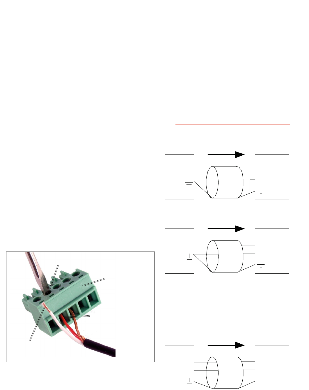
Audio Inputs
Unbalanced Sources
Unbalanced audio sources (positive and ground)
include items such as consumer VCR’s, DVD players,
etc., and may use both two wire and three wire cables.
In either case, the positive output from the source
should be connected to the appropriate positive (+)
inputontheDM84.Theshieldornegative(–)output
shouldbeconnectedtheDM84’snegative(–)input.Two
wire cables should have a jumper between the DM84
negative input and ground. Three wire cables should
have the shield connected to the DM84’s ground input
andtheshieldandnegative(–)leadsjoinedtogetherat
the unbalanced source end.
WARNING: Do not activate phantom power for
unbalanced sources. Refer to online help files
after the software is installed.
DM In
+
-
Source
+
Unbalanced source to DM input
(2-Wire)
Shield
DM In
+
-
Source
+
Unbalanced source to DM input
(3-Wire)
Shield
Balanced Sources
Balanced differential sources from external equipment
and microphones should be wired according to the fol-
lowing illustration. When connecting balanced sources
to the DM84, it is important to not connect chassis
ground (shield) to either signal conductor.
Balanced source to DM input
(3-Wire)
DM In
+
-
Source
+
-
Shield
Installing the DM84 System Into a Rack
The DM84 occupies a single rack space and there are
no special ventilation requirements. Mount with 4 rack
screws using the appropriate mounting holes. It is rec-
ommended to use nylon washers to prevent damage to
the front panel’s finish when tightening the screws.
For North American installations, connect the Power
Cable supplied with the unit between the DM84 and a
stable power source. The DM84 has an internal switch-
ing power supply that can tolerate voltages ranging
from 90 VAC to 240 VAC. Use an approved power cable
for installations outside North America.
Cables
It is recommended to use lacing bars for cable strain
relief when mounting in a rack. Use only professional
audio cable with proper shielding - typically, two con-
ductor plus ground/shield.
Audio Connections
The analog audio inputs and outputs are connected
through 5 pin de-pluggable connectors. Strip the insula-
tionback1/8to3/16”butdonottin(applysolderto)
the leads. Insert the wire into a de-pluggable connec-
tor, leaving less than 1 mm of bare wire exposed, then
tighten the retaining screw.
Caution: Do not over tighten the retaining
screw.
Note the labeling on the DM84 Chassis for the positive
andnegativeleads.Groundissharedbetweentwocon-
nections (the center pin). For balanced connections, all
three leads can be connected.
5-pin depluggable
connector
Do not leave more than
1 mm of exposed wire
beyond the connector.
Do not tin (apply solder to) leads
Retaining Screw
(Do not overtighten)
NOTE:TheDM84doesnothavea“pin1problem.”
Hardware Installation
 (16 pages)
 Manymanuals.com
 Manymanuals.de
 Manymanuals.fr
 Manymanuals.it
 Manymanuals.pl
 Manymanuals.cz
 Manymanuals.es
 Manymanuals-pt.com
Comments to this Manuals