Lectrosonics SPNTWB User Manual Page 10
- Page / 24
- Table of contents
- BOOKMARKS
- IMPORTANT 1
- LECTROSONICS, INC 2
- Important Safety Instructions 3
- Inspection of the Unit 3
- Introduction 4
- Table of Contents 5
- Front Panel 6
- Rear Panel 7
- Hardware Installation 8
- Programmable Inputs 9
- Programmable Outputs 9
- Audio Outputs 9
- Power Amp Outputs 9
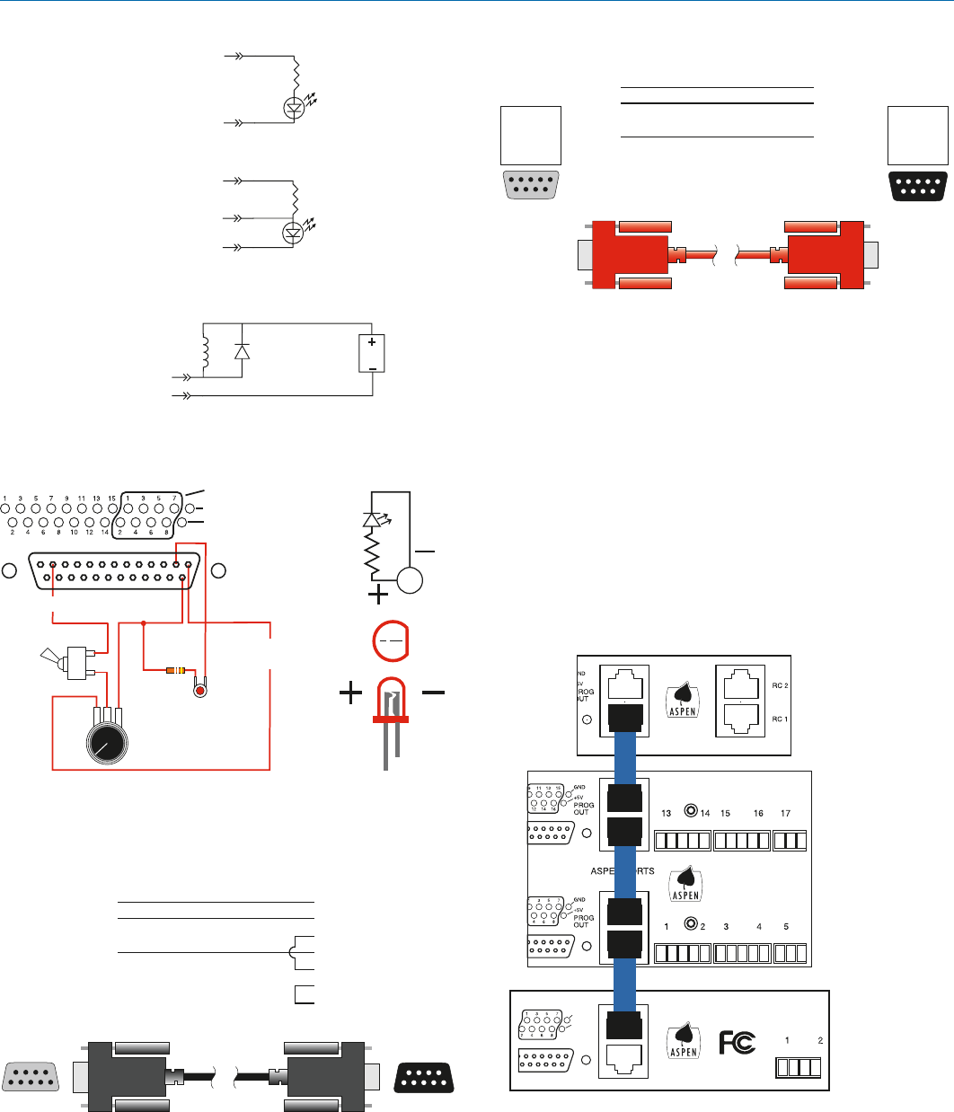
- Crestron 10
- and AMX 10
- Port Wiring Diagram 10
- Cabling Of Stacked Units 10
- Software Installation 11
- Refer to the Help Files 11
- Creating an ASPEN 11
- Installer Disk 11
- Software and Firmware 12
- Firmware Update 12
- Procedure 12
- Update Procedure 13
- Minimum Setup 14
- Stacking Multiple Units 14
- Using the Control Panel 14
- Output Sources 15
- Conference Connections 15
- Acoustic Echo Canceller 15
- The Signal Flow Screen 16
- Rio Rancho, NM 17
- Using the LCD 18
- Master Reset 19
- LCD Categories and 20
- Settings 20
- Network Setup 21
- Web Browser Interface 21
- Service and Repair 22
- INDUSTRY CANADA NOTICE 23
- LIMITED THREE YEAR WARRANTY 24
Related products and manuals for Audio accessories Lectrosonics SPNTWB
 (16 pages)
© 2020, manymanuals.com. All rights reserved. | 0.390 s |
 Manymanuals.com
 Manymanuals.de
 Manymanuals.fr
 Manymanuals.it
 Manymanuals.pl
 Manymanuals.cz
 Manymanuals.es
 Manymanuals-pt.com
Comments to this Manuals