LM/IM
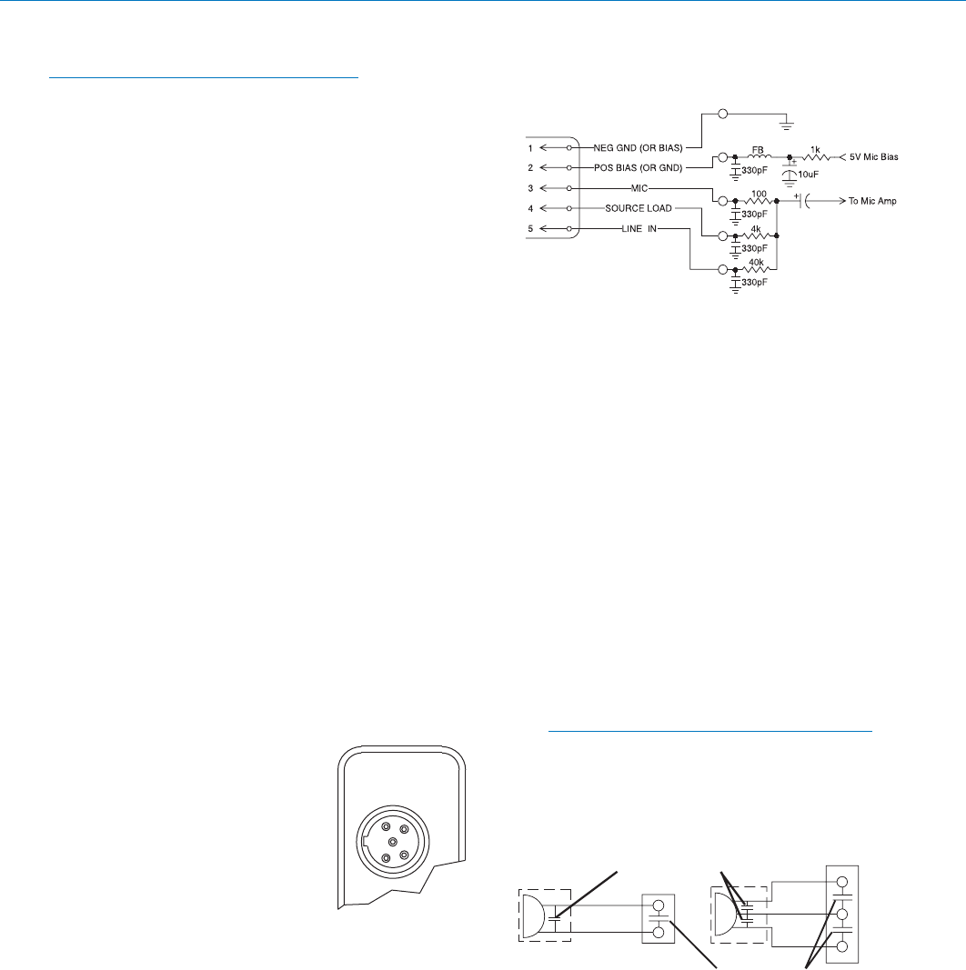
5-Pin Input Jack Wiring
Note: This section does not apply to the IM
transmitter when used as part of the IS400
Instrument System. The cable supplied with the
IS400 Insturment System is prewired and cannot
be field modified. The cable is available in two
configurations, MI33ARA (right angle) and
MI33AST (straight).
The wiring diagrams shown in Wiring Hookups For
Different Sources represent the basic wiring configura-
tions necessary for the most common types of micro-
phones and other audio inputs. Some microphones
may require extra jumpers or a slight variation in the
diagrams shown.
It’s virtually impossible to keep completely up to date on
changes that other manufacturers make to their prod-
ucts. It is possible that you may encounter a micro-
phone that differs from those illustrated. If this occurs
please visit our website and select the
Mic Wiring Info
quick link, or call our toll-free number listed in the back
of this manual for assistance.
When used on a wireless transmitter, the microphone
element is in the proximity of the RF coming from the
transmitter. The nature of electret microphones makes
them sensitive to RF, which can cause problems with
the microphone/transmitter compatibility. If the electret
microphone is not designed properly for use with
wireless transmitters, it may be necessary to install a
chip capacitor in the mic capsule or connector to block
the RF from entering the electret capsule. (See RF
Bypassing.) Obviously, RF bypassing is not a problem
when using the IM transmitter with the IS400 Instru-
ment System.
PIN 1 - Shield (ground) for
positive biased electret lavalliere
LECTROSONICS
microphones. For the increas-
ingly rare negative biased
electret lavalliere microphones, it
is the bias voltage source. It is
also the shield (ground) for
dynamic microphones and line
level inputs.
TRANSMITTER
4
3
2
1
5
PIN 2 - Shield (ground) for
INPUT JACK
negative biased electret lavaliere
microphones. Bias voltage
source for positive biased electret lavaliere micro-
phones.
PIN 3 - Low impedance microphone level input for
dynamic microphones. Also accepts hand-held
electret microphones that have their own battery or
power supply.
PIN 4 - 4 k Ohm source load for non-Lectrosonics
electret microphones. Use in conjunction with other
pins to provide attenuation of high level input
signals.
PIN 5 - 40 k high impedance, line level input for
tape decks, mixer outputs, musical instruments, etc.
Input Circuit
RF Bypassing
Some mics require RF protection to keep the transmit-
ter signal from affecting the capsule, even though the
transmitter input circuitry is already RF bypassed (see
5-Pin Input Jack Wiring schematic diagram above).
If the mic is wired as directed, and you are having
difficulty with squealing, high noise, or poor frequency
response, RF is likely to be the cause.
The best RF protection is accomplished by installing
330 pF bypass capacitors at the mic capsule. If this is
not possible, or if you are still having problems, capaci-
tors can be installed on the mic wires inside the TA5F
connector housing.
The 330 pF capacitors are available from Lectrosonics.
Please specify the part number for the desired lead
style.
Leaded capacitors: P/N 15117
Leadless capacitors: P/N SCC330P
Note: The Lectrosonics M150 lavaliere mic is
already bypassed correctly for use with the LM or
IM transmitters.
2 WIRE MIC 3 WIRE MIC
CAPSULE
CONNECTOR
Alternate locations for bypass capacitors
TA 5F
CONNECTOR
CAPSULE
SHIELD
AUDIO
SHIELD
AUDIO
BIAS
TA5F
Preferred locations for bypass capacitors
LECTROSONICS, INC. 10
 (12 pages)
 Manymanuals.com
 Manymanuals.de
 Manymanuals.fr
 Manymanuals.it
 Manymanuals.pl
 Manymanuals.cz
 Manymanuals.es
 Manymanuals-pt.com
Comments to this Manuals