Lectrosonics Long Ranger IV User Manual Page 11
- Page / 20
- Table of contents
- TROUBLESHOOTING
- BOOKMARKS
- Long Ranger 4 1
- Contents 2
- Rio Rancho, NM 3 3
- Controls and Functions 4
- Front Panel 5
- System Setup 6
- M175 Controls and Functions 8
- M175 Battery Replacement 8
- H187 Controls and Functions 8
- POWER ON/OFF 9
- BATTERY POWER LED 9
- LEVEL CONTROL 9
- H187 Battery Replacement 10
- Using Additional Speakers 10
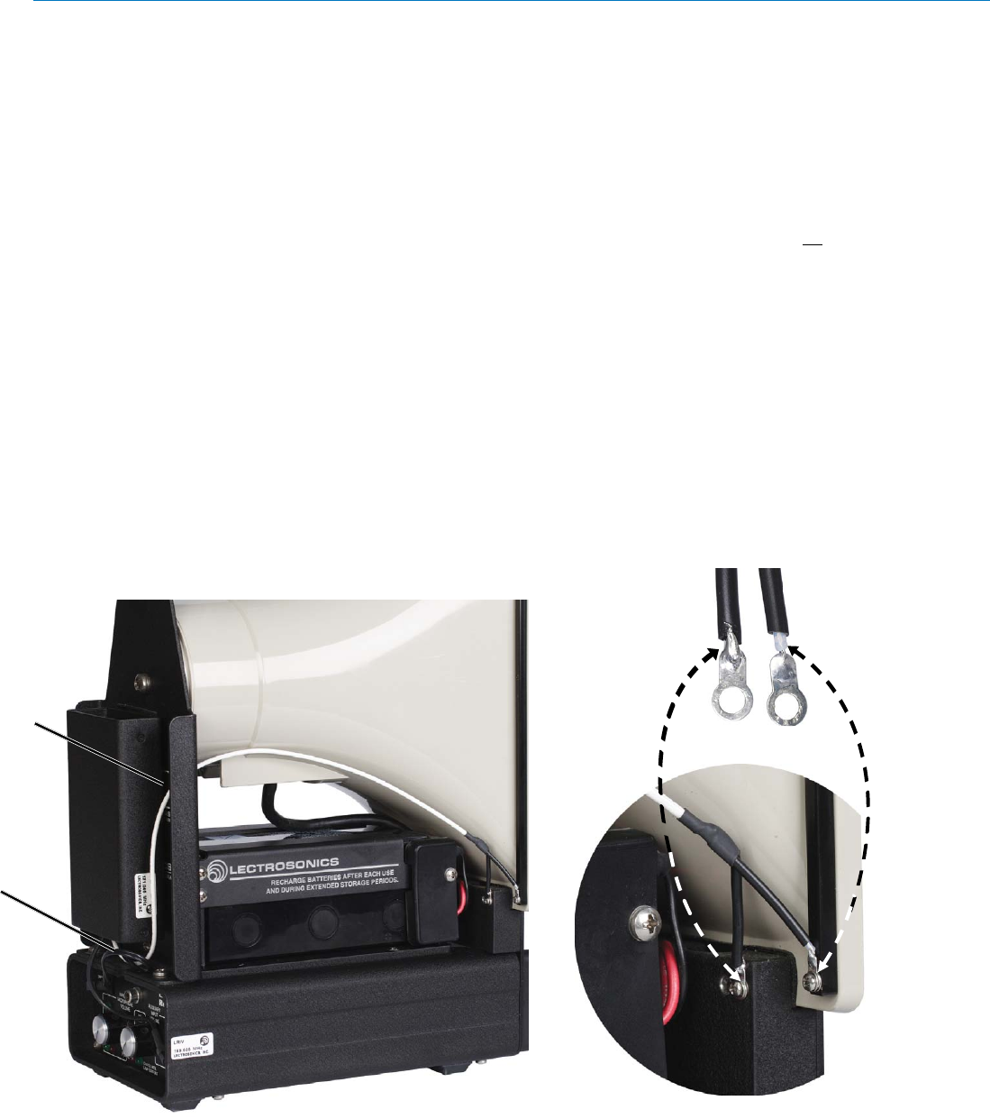
- Figure 4 11
- Antenna 11
- LECTROSONICS, INC. 12 12
- Rio Rancho, NM 13 13
- Specifications 14
- Microphone Choices 14
- Troubleshooting 16
- Service and Repair 17
- LECTROSONICS, INC. 18 18
- Rio Rancho, NM 19 19
- LIMITED ONE YEAR WARRANTY 20
© 2020, manymanuals.com. All rights reserved. | 1.411 s |
 Manymanuals.com
 Manymanuals.de
 Manymanuals.fr
 Manymanuals.it
 Manymanuals.pl
 Manymanuals.cz
 Manymanuals.es
 Manymanuals-pt.com
Comments to this Manuals