Lectrosonics UM400a User Manual Page 10
- Page / 20
- Table of contents
- TROUBLESHOOTING
- BOOKMARKS
- Digital Hybrid Wireless 1
- Technology 1
- Table of Contents 3
- General Technical Description 4
- Controls and Functions 6
- Audio Level Control 7
- Modulation LEDs 7
- Belt Clip 7
- Battery Installation 8
- Operating Instructions 8
- Operating Notes 9
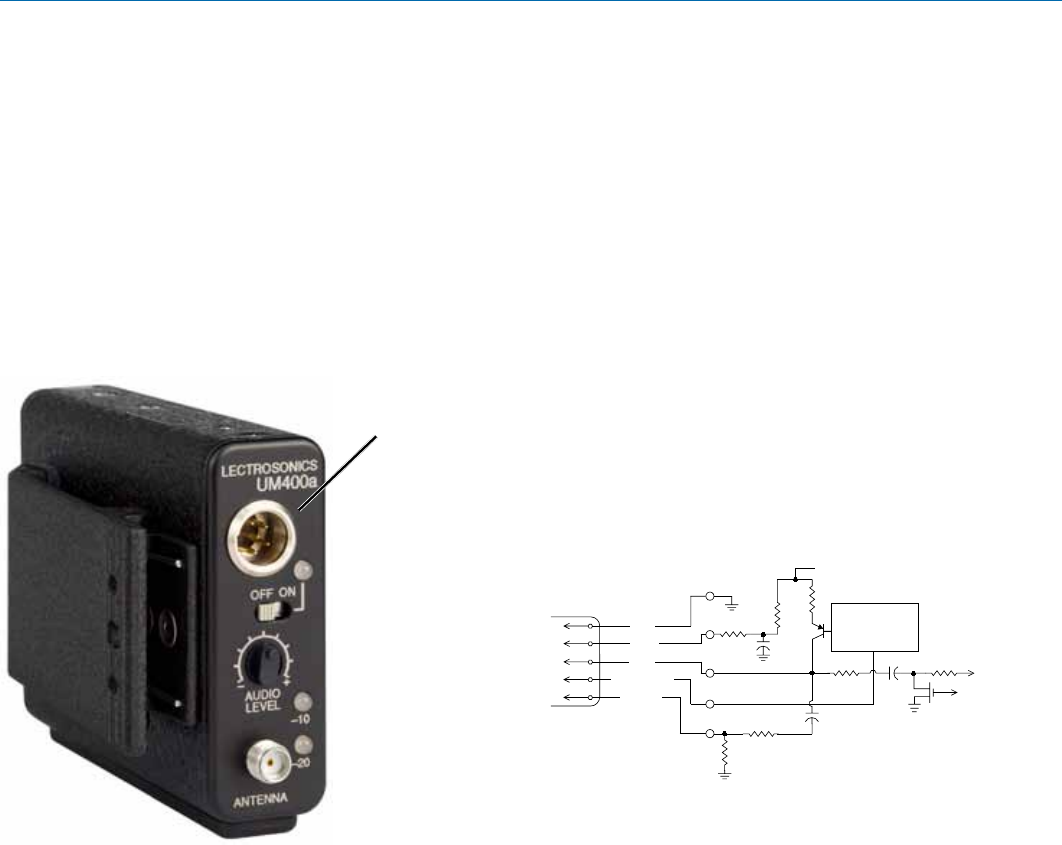
- 5-Pin Input Jack Wiring 10
- Microphone Cable Termination 11
- Microphone RF Bypassing 12
- Line Level Signals 12
- Rio Rancho, NM 13
- LECTROSONICS, INC 14
- Troubleshooting 15
- Specifications and Features 16
- Service and Repair 17
- LIMITED ONE YEAR WARRANTY 20
Related products and manuals for Accessories communication Lectrosonics UM400a
 (8 pages)
© 2020, manymanuals.com. All rights reserved. | 0.529 s |
 Manymanuals.com
 Manymanuals.de
 Manymanuals.fr
 Manymanuals.it
 Manymanuals.pl
 Manymanuals.cz
 Manymanuals.es
 Manymanuals-pt.com
Comments to this Manuals