Lectrosonics SPNDNT User Manual Page 13
- Page / 28
- Table of contents
- BOOKMARKS
- Network Processor 1
- ASPEN Digital Processor 2
- LECTROSONICS, INC 2
- Important Safety Instructions 3
- Table of Contents 4
- Overview 5
- Front Panel 6
- Rear Panel 6
- USB Driver Installation 7
- ASPEN Software 8
- Dante Software 10
- Software 10
- Installation 10
- Mandatory Settings 11
- Hardware Connections 12
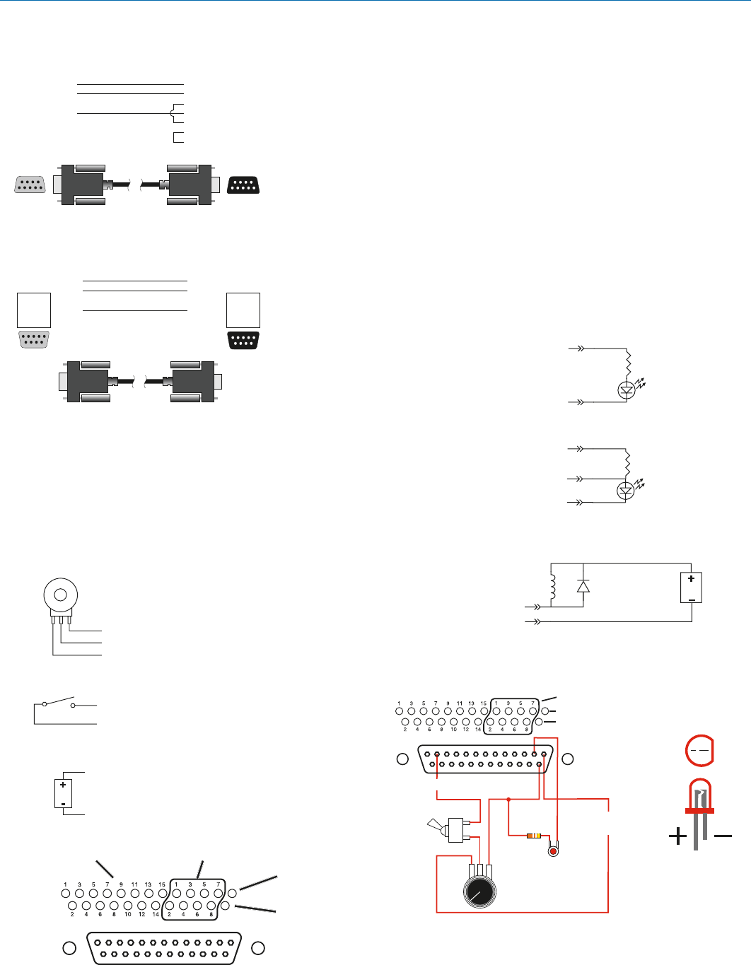
- Programmable Inputs 13
- Programmable Outputs 13
- ASPEN RS-232 Port 13
- Crestron 13
- RS-232 Port Wiring 13
- Network and PC 14
- Connections 14
- SPN 1624 15
- System Setup Examples 16
- SUBSYSTEM A 18
- SUBSYSTEM B 18
- Rio Rancho, NM 21
- Multiple Site Conferencing 22
- FCC Part 15 Compliance 26
- Service and Repair 27
- 13 March 2013 28
Related products and manuals for Audio accessories Lectrosonics SPNDNT
 (16 pages)
© 2020, manymanuals.com. All rights reserved. | 1.141 s |
 Manymanuals.com
 Manymanuals.de
 Manymanuals.fr
 Manymanuals.it
 Manymanuals.pl
 Manymanuals.cz
 Manymanuals.es
 Manymanuals-pt.com
Comments to this Manuals